
Determination of rotation direction of worm wheel and worm gear
Worm and worm gears are usually driven on a 90-degree staggered shaft with the same direction of rotation. If not 90 degrees, they can be different (for example, cylindrical gear hobs are equivalent to worms, cylindrical gears can be rolled in different directions, but the angle of the tool holder must be adjusted, that is the case), but the same is more reasonable.
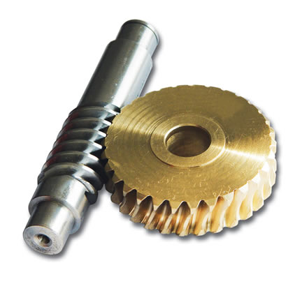
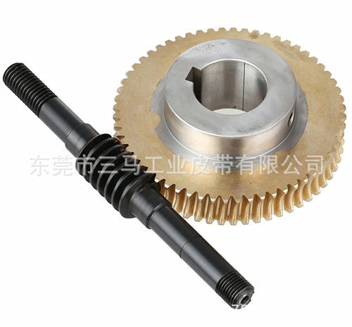
Worm and worm gear drive is used to transfer motion and power between two axles which are neither parallel nor intersecting. In most cases, the two axles intersect at 90 degrees in space, and the transmission power can reach 200 kW, generally below 50 kW. Usually, the worm reduces the speed of the active part (when its reverse stroke is not self-locking, but also the worm gear for the active part for speed-increasing movement), stable transmission; vibration, impact, noise are very small; can be a large speed-down ratio, so the structure is compact. Worm and worm gear drive is widely used in machine tools, automobiles, instruments, lifting and transportation machinery, metallurgical machinery and other departments [1]. The rotation direction of worm gear is usually determined by the relative motion of worm and worm wheels because of the relative position between them, helix direction, worm steering and other factors.
Regard worm 1 as screw, worm gear.
As a local nut, assuming the worm wheel does not move and the worm rotates in the direction shown, the worm should move upward; in fact, the worm can not move, so it can only push down the teeth of the worm wheel which contacts with the worm, so the worm wheel rotates clockwise [2]. This explanation is difficult or inconvenient in practical application. Because there are few literatures on the estimation of worm rotation, the author has worked out some methods in practice.
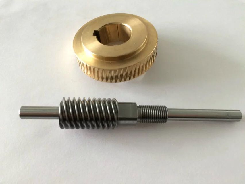
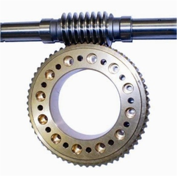
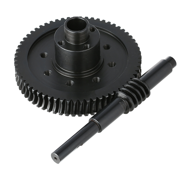
The method of judging the solution can be divided into two steps: 1) judging the direction of worm and worm wheel rotation; 2) judging the direction of worm and worm wheel according to the relative position relationship of worm and worm wheel and the direction of worm rotation. 1.1 The judgment of the direction of rotation of worm and worm gear is divided into left and right rotation, usually right rotation, and the judgment of the direction of rotation is similar to helical cylindrical gear. The axis of the worm or worm wheel is placed straight, the left side of the helix is high, the right is low, the left is low, the right is high and the left is low. For example, figure 1, the worm helix is right high and left low, so it is a right-handed example. As shown in Fig. 2, the helix of the worm is left high and right low, so it is left-handed. 1.2 Turning judgment of worm gear 1) Using the force state to judge: In worm and worm gear transmission, the axial force Fa1 of the active worm and the circumferential force Ft2 of the driven worm gear are a pair of force and reaction force. On the premise of obtaining the axial force direction of the worm, the circumferential force direction of the worm wheel can be obtained, and this force is exactly the force driving the worm wheel to rotate, and then the direction of the worm wheel can be obtained.
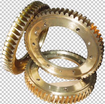
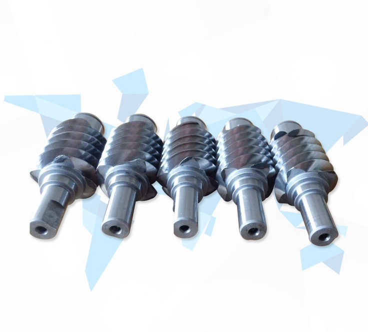
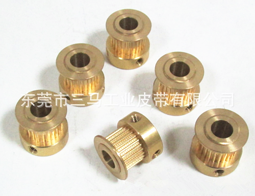
Reducer Accessories Machining Center Spot supply: gear processing, gear motor, gear processing, worm gear and worm, MB CVT, gear commutator, worm gear reducer, screw elevator, micro cycloid pinwheel reducer, precision planetary reducer, spiral bevel gear reducer, helical gear hard tooth surface reducer, gear reducer parts processing
Worm and worm gears are usually driven on a 90-degree staggered shaft with the same direction of rotation. If not 90 degrees, they can be different (for example, cylindrical gear hobs are equivalent to worms, cylindrical gears can be rolled in different directions, but the angle of the tool holder must be adjusted, that is the case), but the same is more reasonable.
Worm and worm gear drive is used to transfer motion and power between two axles which are neither parallel nor intersecting. In most cases, the two axles intersect at 90 degrees in space, and the transmission power can reach 200 kW, generally below 50 kW. Usually, the worm reduces the speed of the active part (when its reverse stroke is not self-locking, but also the worm gear for the active part for speed-increasing movement), stable transmission; vibration, impact, noise are very small; can be a large speed-down ratio, so the structure is compact. Worm and worm gear drive is widely used in machine tools, automobiles, instruments, lifting and transportation machinery, metallurgical machinery and other departments [1]. The rotation direction of worm gear is usually determined by the relative motion of worm and worm wheels because of the relative position between them, helix direction, worm steering and other factors.
Regard worm 1 as screw, worm gear.
As a local nut, assuming the worm wheel does not move and the worm rotates in the direction shown, the worm should move upward; in fact, the worm can not move, so it can only push down the teeth of the worm wheel which contacts with the worm, so the worm wheel rotates clockwise [2]. This explanation is difficult or inconvenient in practical application. Because there are few literatures on the estimation of worm rotation, the author has worked out some methods in practice.
The method of judging the solution can be divided into two steps: 1) judging the direction of worm and worm wheel rotation; 2) judging the direction of worm and worm wheel according to the relative position relationship of worm and worm wheel and the direction of worm rotation. 1.1 The judgment of the direction of rotation of worm and worm gear is divided into left and right rotation, usually right rotation, and the judgment of the direction of rotation is similar to helical cylindrical gear. The axis of the worm or worm wheel is placed straight, the left side of the helix is high, the right is low, the left is low, the right is high and the left is low. For example, figure 1, the worm helix is right high and left low, so it is a right-handed example. As shown in Fig. 2, the helix of the worm is left high and right low, so it is left-handed. 1.2 Turning judgment of worm gear 1) Using the force state to judge: In worm and worm gear transmission, the axial force Fa1 of the active worm and the circumferential force Ft2 of the driven worm gear are a pair of force and reaction force. On the premise of obtaining the axial force direction of the worm, the circumferential force direction of the worm wheel can be obtained, and this force is exactly the force driving the worm wheel to rotate, and then the direction of the worm wheel can be obtained.
Reducer Accessories Machining Center Spot supply: gear processing, gear motor, gear processing, worm gear and worm, MB CVT, gear commutator, worm gear reducer, screw elevator, micro cycloid pinwheel reducer, precision planetary reducer, spiral bevel gear reducer, helical gear hard tooth surface reducer, gear reducer parts processing
Next:
General causes of abnormal vibration of worm gear reducer Previous:
Causes of abnormal vibration in worm gear reducer production

News Center
Commend Products
Contact
 Hotline
400-026-9834